Modbus communication is a widely used protocol in industrial automation for connecting PLCs, HMIs, sensors, and other devices. Siemens S7-1200 PLCs, with the CB1241 communication board, offer seamless integration with Modbus RTU devices. In this blog, I’ll guide you through the configuration of the CB1241 Modbus communication board with an S7-1200 PLC using TIA Portal.
Video Tutorial
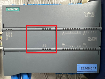
Step 1: Understanding the CB1241 Module
The CB1241 communication board enables the S7-1200 PLC to communicate with other devices using the Modbus RTU protocol. The module can be attached to the add-on-board option of the S7-1200 CPU and supports serial communication via RS485.
- Supported Protocols: Modbus RTU, ASCII
- Connector Type: RS485 (Screw Terminals)
- Communication Rate: Up to 115.2 kbps
Step 2: Hardware Setup
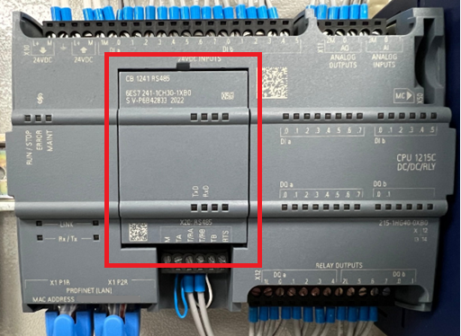
Mounting the CB1241 Module:
- Connect the CB1241 communication board to the Add-on Board of the S7-1200 PLC. Ensure it is securely attached and powered by the PLC.
Wiring the RS485 Network:
- Connect the CB1241 module’s RS485 terminals to the Modbus network. Ensure proper termination and grounding for noise reduction, especially in long communication lines.
Step 3: Configuring TIA Portal for Modbus Communication
1. Creating a New Project:
- Open TIA Portal, and create a new project for the S7-1200 PLC. Select the appropriate CPU model.
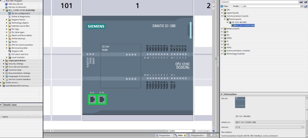
2. Adding the CB1241 Module:
- In the project tree, right-click on the “PLC” and choose Add New Device.
- Under Communication Boards, find CB1241 and add it to the hardware configuration.
3. Configuring the Modbus Parameters:
- Double-click on the CB1241 module in the hardware configuration to configure the communication parameters (baud rate, parity, data bits, and stop bits) to match the Modbus RTU master or slave device.
- Typical settings include:
- Baud rate: 9600 bps
- Data bits: 8
- Parity: Even
- Stop bits: 1
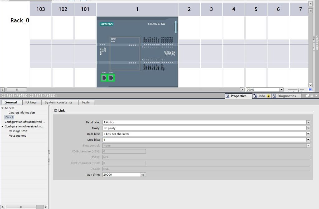
The above settings depend on the Slave device settings or can be the same if the slave supports the above communication settings.
Step 4: Configuring Modbus RTU Communication in the Program
- Modbus Library Installation:
- Siemens provides a free Modbus library for S7-1200, which simplifies Modbus communication. Download the Modbus RTU library from Siemens’ website if not already installed.
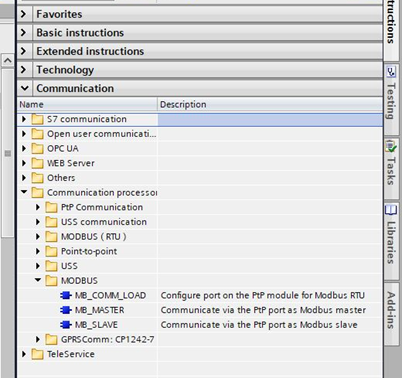
- Modbus Master/Slave Function Blocks:
- Open the Modbus library in TIA Portal and add the Modbus_Master or Modbus_Slave function blocks to your program, depending on the role of the PLC.
- If the PLC is the master, the function block will poll data from the slave devices (e.g., VFDs, meters).
- For slave devices, the PLC responds to requests from the Modbus master (e.g., a SCADA system or another PLC).
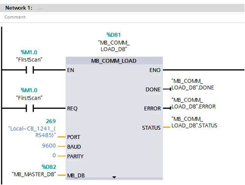
- Configuring the Modbus Function Blocks:
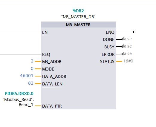
- In the Modbus_Master block, configure the parameters:
- COMM_ID: The ID of the communication module (CB1241).
- Node Address: The Modbus address of the slave device.
- Function Code: The Modbus function to execute (e.g., Read Holding Registers, Write Coils).
- Start Address: The starting register address in the slave.
- Quantity: The number of registers or coils to read or write.
- Data: A pointer to the memory location where the data will be stored or fetched from.
Step 5: Testing and Troubleshooting
- Download the Program:
- After configuring the Modbus function blocks and mapping the registers to appropriate data blocks, download the program to the PLC.
- Monitoring Communication:
- Use TIA Portal’s online monitoring tools to observe the status of the Modbus communication. Look for any errors or misconfigurations in the communication parameters.
- Use Diagnostic Buffer in the PLC to check for communication errors, such as incorrect baud rate or mismatched node addresses.
- Testing with Modbus Devices:
- If the PLC is the Modbus master, initiate a read or write request and monitor the data exchange with the slave devices.
- For slave configurations, use a Modbus master simulator to send requests and verify the PLC’s response.
Step 6: Optimizing and Fine-Tuning
Once the basic communication is established, you can:
- Optimize communication by adjusting the polling interval and data size to reduce network load.
- Implement error handling using status bits from the Modbus function blocks to detect timeouts, CRC errors, or invalid responses.
- Test communication under varying loads to ensure stability.
Conclusion
Configuring the CB1241 Modbus module with the S7-1200 PLC opens up the possibility of integrating third-party Modbus RTU devices into your Siemens automation system. By following the steps outlined above, you can easily establish communication, configure parameters, and test your system in TIA Portal. Once the setup is complete, ensure to thoroughly test and fine-tune the communication to meet your application’s specific needs.
Feel free to reach out in case of specific implementation challenges, and keep exploring the versatile communication options that Siemens and Modbus offer in industrial automation!

Senior Tech Manager at IIPD Global, weaving magic in Industrial, Building, and home Automation. KNX Tutor on a mission! Embracing Industry 4.0 and proudly shaping the tech landscape. Certified by CertNexus to ignite minds!